Paul Guy
COMM3F : NS2 Tutorial:
COMM3F
Network Simulation
(Ian Fletcher & John Tindle).
Ns2 Tutorial
Paul Guy
3rd December 2003
2. Background for Ns2
2.1. Node types
Nodes in Ns are the hardware entities (hosts) within a simulation topology. Each simulation requires an instance of the simulator class. Nodes are defined in a standalone class in Otcl. Two basic node types exist unicast and multicast, which contain components that are TclObjects, which give them the correct functionality for routing in a particular simulation.
The node can be configured to customise it for example to create a mobile node in a wireless topology. Unicast is the default in Ns. Nodes contain a node entry object and classifiers but to get started the two main classifiers defined for a node that are of concern here are an address classifier and a port classifier which ensure incoming packets are sent to the correct agent or outgoing link. This gives us our first two key words “Agent” and “Link” which allows us to look at a basic node. In the diagram below there are two nodes, which have a link. The link can be either simplex or duplex.
You will notice that each node has an agent attached; this is the connection / protocol, which could be TCP. On top of this agent sits an application, which puts traffic onto our network such as FTP. An agent is normally software based.
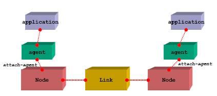
[Fig-1. Node Construction [RED01]]
An agent comes in two flavours, a Source agent and a sink agent. The source agent is the generator of packet data and the sink node is the destination of the packet data. Lets call our nodes node1 on the left and node2 on the right.
If TCP was added to node1 making it a source agent and we needed to send data to node2 a TCPsink agent would have to be attached to node2. Once the two agents are attached an explicit declaration is required to connect the two nodes. Alternatively UDP could have been used on node1 and a null agent sink on node2.
So a node has agents attached and applications attached to the agent only certain applications should be attached to certain agents for example UDP and CBR we will discuss CBR in more detail later. A node can have one or more links. A node can be a source or sink node or even both depending on the topology.
2.2. 20 network protocols
A layer 3 Protocol. Comes in two versions IPV4, IPV6. This is a data-oriented protocol that communicates data across a network that is used by both source and host.
TCP Transmission Control Protocol
IETF RFC 793 defines TCP. TCP is a connection-oriented protocol. A highly reliable protocol that guarantees delivery. That is normally associated with IP in the TCP/IP model.
UDP User Datagram Protocol
IETF RFC 768 defines the UDP transport protocol. UDP does not guarantee delivery of a message.
HTTP Hyper Text Transfer Protocol
Is a request response protocol used on the World Wide Web (WWW). Maintained by the W3C org. Defined in RFC2068.
POP3 Post Office Protocol version 3
Used to retrieve emails from a server for a local client over TCP/IP. Various RFC’s exist for POP3
SNMP Simple Network Management Protocol
Used to monitor network-attached devices for conditions.
SMTP Simple Mail Transfer Protocol
Used for e-mail transmission across the Internet.
SSH Secure Shell
Is an application and a protocol. Used for executing commands on a remote computer.
IMAP Internet Message Access Protocol
Used for retrieving e-mails from a remote server. It leaves a copy on the server as opposed to deleting.
NNTP Network News Transfer Protocol
Used by the Usenet Internet service.
LDAP Lightweight Directory Access Protocol
Used for accessing online directory services.
DHCP Dynamic Host Control Protocol
Dynamically Allocates IP addresses to clients on a LAN.
SPX Sequenced Packet Exchange.
A Novell protocol used to manage Internet Package Exchange (IPX).
BGP Border Gateway Protocol
Routing Protocol on the Internet. Used by ISP’s
EIGRP Enhanced Interior Gateway Routing Protocol
Cisco routing protocol based on IGRP but can deal with classless interdomian routing
IGRP Interior Gateway Routing Protocol
IGRP is a distance vector routing protocol designed by Cisco. Used by routers to exchange routing data.
RIP Routing Information protocol
Allows routers to adapt dynamically to changing network connections
PPTP Point to Point Tunnelling Protocol
Used to establish a connection between two computers using a phone line.
ARP Address Resolution Protocol
Is a method of finding a hosts Ethernet MAC address from its IP address
MARS Multicast Address Resolution Server
Multicasting is where a source sends a packet simultaneously to multiple destinations.
2.3. Typical applications
Two common applications that are used in Ns, which most will have heard of are FTP and Telnet. When we use these applications from a home or business Pc / workstation, we are in fact using the client or traffic source part of the application. All forms of users from various locations use FTP widely and this client software can be by different vendors. To transfer a file-using FTP we put traffic on the network, but in order for us to complete this we need to connect to a FTP server (FTP daemon) or the sink node.
Telnet works with the same type of principle in that it uses TCP as the agent with a client application and traffic is placed on the on the network for example to gain a remote login to a server (sink node). Other examples of typical applications are e-mail using SMTP all senders are using a client (agent) which then transfers your e-mail by putting traffic on the network to connect via a e-mail server (sink node).
This sink node may if required then become an agent to pass on the data to another sink node, before the person you sent the e-mail to, client application requests the e-mail you sent from the sink node. HTTP is another example using a web browser as a client, which puts traffic on the network to connect to a web server (sink node). The more you think about it the more applications you could add to the list.
2.4. Constant bit rate (CBR) data transfer
CBR reserves a constant amount of bandwidth during the connection set up even when idle. The CBR service was conceived to support applications such as voice and video, which require jitter (small time variations).
The source may send at a negotiated or lower rate at any time and for any duration. The connection in Ns would normally be set up with a UDP agent and the traffic source would be CBR. In the diagram below node0 and 1 are both using UDP and CBR, which are sending data via node2 to the null agent sink node3.
There is bandwidth congestion at node2 which means packets of data are being dropped for example using a drop tail queue. This results in node3 not receiving all the data.
[Fig-2 Drop tail queue [MGT01]]
In CBR when packets are lost they are not re transmitted as receiving packets late in a voice or video stream is of no use. The human eye and mind will normally fill in any small gaps. This is one reason why CBR may run over UDP as there is no need to receive an acknowledgement. For streams of data that require some form of order, TCP should be used.
2.5. Traffic generator function
So far we have covered node types, agents, applications and that we attach or link the objects in a simulation. An overview was given of CBR, which is a traffic source and that packets of data were sent across the network. Let us now look at how the traffic is put on the network with a typical traffic generator function. First off we create our simulation and set up the topology this will be discussed later. In order to put traffic on a network we need to attach an agent to a node and attach the application to the agent and link the source and sink nodes.
Set up a UDP connection with a variable name of udp and attach the UDP agent (variable name $udp) to node1 (variable name $n1).
set udp [new Agent/UDP]
$ns attach-agent $n1 $udp
Set up a null agent sink node with a variable name of null. Attach the null agent (variable name $null) to node3 (variable name $n3). Then connect the traffic source node (node1) to our sink node (node3).
set null [new Agent/Null]
$ns attach-agent $n3 $null
$ns connect $udp $null
Set up a CBR over a UDP connection. Each Traffic source has various attributes, for example the packet size is set to 1000 bytes.
set cbr [new Application/Traffic/CBR]
$cbr attach-agent $udp
$cbr set packet_size_ 1000
Schedule events for the CBR agent i.e. tell it when to send data and when to stop.
$ns at 0.1 "$cbr start"
$ns at 5.0 "$cbr stop"